
 Deutsch
For several years now the term ‘Internet of Things’ has been in common parlance. Devices that are part of the ‘IoT’ can communicate with each other wirelessly. This is generally achieved using current standards such as WiFi, Bluetooth, Zigbee, and 5G. The Internet of Things also changes the requirements placed on the devices themselves. Today every smartphone is a connection node to other devices. Smart Home applications and the Smart Watch on the wrist are just two of numerous examples.
For all this to work smoothly, however, every component must be matched to the requirements of the wireless environment. This is also true for the tiny quartz crystals and oscillators that provide the clock signal in many electronic applications. So the question arises: what needs to be taken into account in the use of quartz crystals and oscillators in IoT applications?
Increasingly small products require ever-smaller components
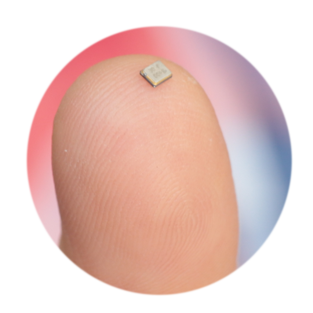
In recent years the availability of ever-smaller, battery-powered applications and wearables has grown sharply, notably in the consumer electronics sector. The products themselves, and thus also the circuit boards and components within them, are growing ever smaller. This trend is referred to as ‘miniaturization’. And for many products, including those of major IC manufacturers, no end is in sight for this trend, and this has implications for other components – including our quartz crystals and oscillators
As a consequence of this, changes are occurring to the requirements placed on the housing and specifications of passive components – which also have to be ever smaller. There are also advantages here; on the one hand, less raw material is required, which is good for the environment. On the other, the costs for packaging, transportation, and storage are reduced.
One challenge faced by this trend is however the physical limitation in respect of the frequency itself. To obtain a low frequency of oscillation, the development process begins with a thick piece of quartz, whereas a higher frequency is obtained from a thinner crystal. The ratio of surface area to thickness, meanwhile, must not fall below a certain value, otherwise the electrical parameters become unfavorable. Conversely, this means that with very small sizes, low frequencies (i.e. with thick crystals) cannot be generated effectively. This limitation primarily affects quartz crystals and not quartz oscillators, as the latter contain an IC that can generally divide the frequency down. As a consequence, oscillators have a wider scope of possibilities in regard to frequency. Additionally, some oscillators can also achieve significantly higher frequencies because the IC can multiply up the natural frequency of the crystal.
As a rule, quartz crystals are operated in what is known as a ‘Pierce circuit’. The illustration of the basic circuit elements shows that this consists essentially of two parts.
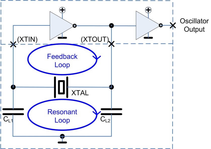
These are the resonance
loop, in which the original oscillation takes place, and the feedback loop that
excites the circuit into oscillation and then feeds in energy to compensate for
losses in the circuit.
The quartz crystal in the resonance loop ensures that the oscillation occurs
only at its resonant frequency since it provides its best quality only at this
frequency.
Reliable initiation of oscillation with a minimum of energy
Many small battery-powered devices are based on ‘system-on-chip’ (SoC) components. In these applications, power consumption is a crucial factor. Yet low power consumption is often achieved today by using a low operating voltage. This in turn has a negative effect on the reliability of oscillation of the quartz circuit. To compensate for this negative effect, the developer must pay particular attention to the choice of components and the best possible matching of the circuit.
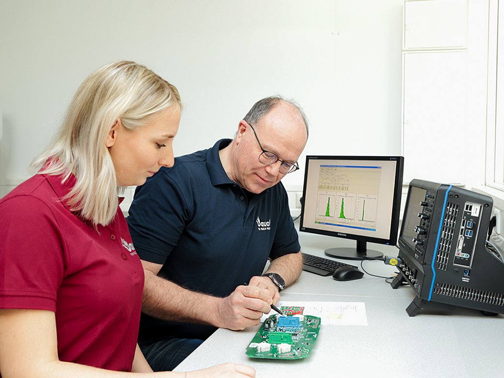
To compensate for the negative impacts on the oscillation safety factor posed by smaller components and the low supply voltage, a reduced nominal load capacitance for the crystal is often selected. A circuit with a smaller CL can often also be used with weaker driver stages and still achieve acceptable oscillation reliability levels. During the matching process in the laboratory, the developer examines the frequency accuracy, oscillation safety factor and the output from the crystal to ensure a high level of operational reliability in the field. Jauch Quartz GmbH offers these analyses to its clients in order to provide support to developers working with these tasks.
Highest frequency accuracy for wireless applications
A major requirement for quartz crystals in wireless applications is naturally their frequency accuracy. Circuits are normally assigned radio wavelengths in narrow frequency bands. To prevent interference from other frequencies and also to enable connections over longer ranges, it is important that any wandering from the nominal frequency is kept to a minimum. In Bluetooth, for example, the maximum permitted frequency deviation is ± 40 parts per million (ppm). This limit must not be exceeded at any point during the entire lifetime of the application under any circumstances. To ensure this, the developer must estimate all possible influences using a worst-case calculation, thus, in particular:
- Tolerance at 25°C
- Stability across the expected temperature range
- Error resulting from mismatch of circuit CL
- Long-term changes
- Error resulting from tolerance of load capacitance (= CL deviation)
- CL tolerances of pin capacitances on the IC, plus PCB tolerances
To ensure frequency compliance at 25°C, the load capacitance for each quartz component is defined in the specification. The load capacitance is the capacitance to which a quartz crystal is most exactly matched during production. Here the crystal is excited into oscillation, the frequency is measured and if necessary the mass of the silver electrode is corrected by evaporation deposition or erosion (by bombardment with ions).
If the active CL is achieved again exactly during this matching in the final circuit, the crystal will oscillate reliably at room temperature at its nominal frequency.
For developers, this matching brings with it the problem that they usually do not know what error is being introduced to the measurement by the crystal currently being used. Without knowing this, it is impossible to perform a precise matching. If the matching is performed in the laboratory of the quartz supplier, it is generally the frequency deviation brought by the individual crystal that is measured and subsequently compensated. Alternatively, developers who wish to make a precise matching themselves can obtain measured samples from the supplier so that the errors introduced can be compensated.
The correct resistance for error-free functioning
So, crystals must be small and must operate as precisely as possible. A further factor is that the equivalent series resistance (ESR) of the crystal must be kept low. The ESR describes the ohmic resistance in the equivalent circuit represented by the quartz crystal at resonance. Data sheets normally specify a maximum ESR that the manufacturer undertakes not to exceed. This ESRmax directly affects the oscillation safety factor (OSF) of the circuit and should therefore be as low as possible.
Nevertheless, the smaller the crystal is, in general the higher is the ESRmax. Another rule: the smaller the crystal, the less power it can receive without overloading.
Use of modern quartz types in older circuits: re-designs
The issue of power leads to another problem that is not restricted to IoT applications. Many re-design projects are today coming up against the problem that older and larger sizes of quartz components are being discontinued owing to lack of availability of the earlier products. The developer is therefore often faced with the problem of having to re-design a circuit that was released in the past with a large crystal type in order to operate it with a smaller, currently available crystal. Particular attention here has to be given to the power-handling capacity of the crystal. Where possible this should be checked by measurement. This enables the developer, on the one hand, to be certain that the crystal will be operated within its harmonic range and thus as loss-free as possible with the specification agreed. On the other hand, excessive ageing of the quartz crystal, and in the worst case, failure due to overload, is prevented.
Which quartz products are particularly well-suited to use in IoT applications?
In principle, both quartz crystals and quartz oscillators are equally suitable. Both are capable of achieving the required frequency stability.
Where the application involves large volumes, quartz crystals are generally chosen for commercial reasons. However, many tasks are involved at the development stage in order to ensure that the result is a stable, reliably functioning product. In contrast to this is the costlier oscillator, which comes with its manufacturer’s guarantee that all parameters are met. This option offers maximum precision, coupled with high operational reliability – and all this with relatively little development outlay.
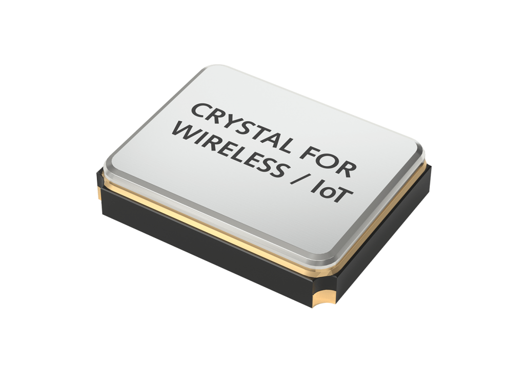
To be able to fulfill all the demanding requirements placed on a precise quartz clock signal, special quartz crystal series have been created such as the Jauch JXS-WA crystals for wireless applications (WA). The electrical parameters of these products have been particularly optimized, and thanks to special pre-treatment they exhibit a particularly low level of long-term aging.
Finally, mention should be made of the ‘tuning-fork’ quartz crystal (also known as clock crystal) that is often also used and normally oscillates at 32,768 Hz. Many ICs offer the option of connecting an additional crystal as a standby clock generator. This offers the possibility of allowing the high-frequency clock to rest during standby phases of the application, thereby reducing power consumption by the IC significantly. The IC continues meanwhile to run in parts at 32,768 Hz and is thus able to return to power mode quickly. Owing to their relatively high temperature sensitivity, clock crystals are not regarded as a sufficiently precise clock for wireless applications. Thanks to their significantly lower current consumption of just a few µA, however, they are considered an ideal addition for the standby mode that is often required. This aside, these clock crystals are of course also suitable for all traditional real-time clock applications.
Do you need technical support or do you have questions about your frequency control component? Feel free to contact us.


