
 Deutsch
Many engineers do not spend much thought on quartz crystals while designing their oscillator circuit. For them, it is a standard feature that will work anyway. In fact, it’s not that simple.
The oscillator circuit sets the heartbeat of the application and requires a careful matching between the quartz crystal and its other components. Otherwise the accuracy of the generated frequency suffers and the application may even fail in the field.
We at Jauch want to spare our customers such problems. Therefore, we do detailed analyses of our customers’ oscillator circuits, aiming at an optimal match between crystal and circuit. The following three parameters are examined in the course of these so called “OSF Tests”:
1) Frequency Accuracy
2) Oscillation Safety Factor (OSF)
3) Drive Level
Frequency Accuracy
The main task of an oscillator circuit is to produce a stable and accurate frequency over the entire application period and under all environmental conditions. For this to succeed the total load capacitance (CL) of the oscillator circuit must be as close as possible to the nominal load capacitance (nominal CL) of the crystal or ideally match it.
Accordingly, the first step in the circuit analysis is to determine the total load capacitance (CL) that the quartz crystal “sees” at its two terminals. Since any direct contact with the circuit would falsify the measurement results, the measurement is carried out without contact using a near-field probe that is placed at a small distance above the circuit. The crystal is then soldered out of the circuit and measured with a Crystal Network Analyzer at nominal CL.
The greater the deviation of the total CL from the nominal CL of the crystal, the greater the frequency deviation. However, by examining the crystal in the analyzer, it is possible to determine what corrections are necessary to improve the frequency accuracy of the circuit.
Oscillation Safety Factor (OSF)
In a second step, the oscillation safety of the oscillator circuit is checked. This term describes the circuit’s ability to start up quickly and reliably under all conceivable ambient conditions. The analysis therefore focuses on electronic resistance within the circuit.
As you can see in Figure 1, a new additional resistor (R Pot) is built into the circuit in series with the quartz. The resistance of R Pot is then increased step by step until the oscillation stops. This method simulates a “worst-case quartz” and reveals the maximum permissible impedance for the quartz in the particular oscillator circuit.

The ratio of the maximum impedance determined in this way and the ESR,max of the crystal ultimately results in the oscillation safety factor (OSF).
For MHz crystals (AT-Cut), an OSF greater than 5 is considered sufficient for most standard applications. For safety-relevant applications, such as those found in the automotive sector or in medical technology, an OSF greater than 10 is usually required.
For KHz crystals, OSF values between 3 and 5 must already be rated as good, and values greater than 5 as very good, due to the design these circuits for very low power consumption.
Drive Level
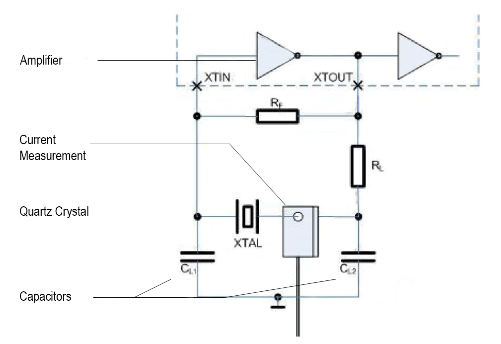
In order to prevent an overload of the quartz, it is determined which power is acting on it. For this purpose, the first step is to measure the strength of the current flowing through the quartz using a HF current clamp (Fig. 2). The “Drive Level” of the quartz is calculated from this measurement result and the parameters of the circuit already determined. The Drive Level must not exceed the maximum value specified in the quartz data sheet.
Exceeding the maximum Drive Level may lead to frequency deviations or, in the worst case, even to failure of the quartz.
Adapting the Oscillator Circuit
An oscillator circuit that passes all three tests to satisfaction can be integrated into the intended application with a good conscience. However, if the tests reveal deficits, the circuit must be adapted. For example, if there are problems with frequency accuracy, a variation of the load capacitors in the circuit can reduce the difference between circuit CL and nominal CL of the quartz crystal and thus improve the frequency accuracy. Sometimes it is also necessary to replace the originally installed crystal with another type.
Any change to the circuit means that all the tests listed here must be carried out again. This makes the search for the perfect match between the quartz and the circuit a tinkering job that takes several hours. Due to the small size of the components, much of the work is done under the microscope.
After completion of the OSF test, Jauch provides its customers with a detailed test report. This report contains all important measured values and, if required, also contains clear recommendations for adapting the circuit. In this way, any problems are often detected and avoided before series production starts.


